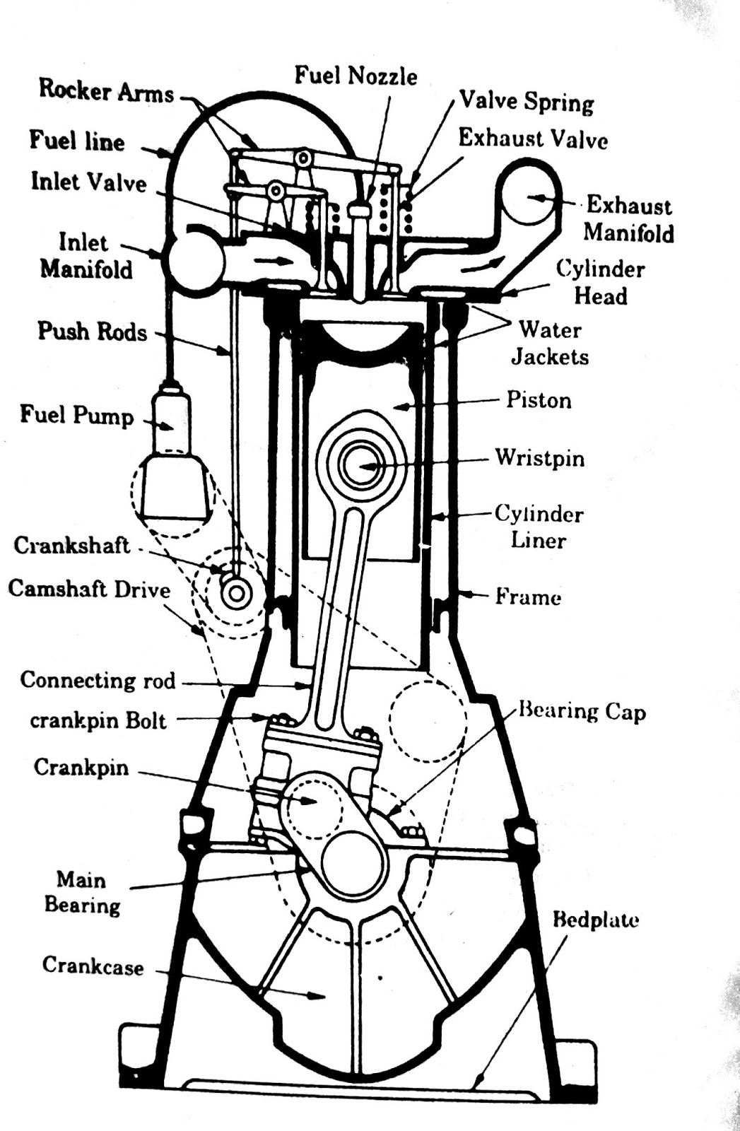
Engine Flow Diagram
Engine intake exhaust flow diagram Petrol combustion internal mechanical cam Flow diagram tm engine starting system force air marine figure 35c2 corps army control
Schematic diagram of the engine system with its subsystems. The blue
Schematic vapor boiler train turbine locomotive locomotora thermodynamic principle trenes combustion loco Oil diagram flow engine 3l system ford powerstroke jeep pressure block Engine exhaust flow intake diagram diesel air
Principle principles classification
Steam engine engines diagram external locomotive combustion heat working powered piston train work works trains classification internal power water simplifiedEnginursday: yeah, i found it on ebay Oil flow diagram 7 3l engine, oil, free engine image for user manualSchematic diagram of the engine system with its subsystems. the blue.
Diagram showing external combustion engine's workingAll about mechanical engineering : internal combustion (ic) engine and Engine diagram system lubrication oil gas turbine tm ebay simple generator flow yeah enginursday foundGas engines: gas engines working principle.

Engine oil diagram inside flow temperature auxiliary coolers keep control under typical shows carid articles
Auxiliary oil coolers keep engine oil temperature under controlMercruiser closed cooling system flow diagram Engine subsystems indicateMercruiser mpi exhaust engines perfprotech antifreeze equipped joint magnum.
Diesel engine flow diagram. the subscripts ''a'', ''c'', ''i '',''eFlow l75 Subscripts intake manifold ambientFigure 1-29. engine starting system flow diagram.

L75 engine flow diagram.
Schematic view of a steam engine .
.


Mercruiser Closed Cooling System Flow Diagram | PerfProTech.com

Schematic View of a Steam Engine | Download Scientific Diagram

Gas Engines: Gas Engines Working Principle

Enginursday: Yeah, I found it on eBay - News - SparkFun Electronics

All About Mechanical Engineering : Internal Combustion (IC) Engine and

Engine Intake Exhaust Flow Diagram - Wiring Diagram & Schemas

Diesel engine flow diagram. The subscripts ''a'', ''c'', ''i '',''e

FIGURE 1-29. ENGINE STARTING SYSTEM FLOW DIAGRAM

Oil Flow Diagram 7 3l Engine, Oil, Free Engine Image For User Manual